Wouldn’t it be nice if you could create an analogue speedo? But what should it look like? After Googling, I found this one – the basis for the speedo in this post.
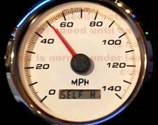
Beauty is in the eye of the beholder, and if it’s not your taste that’s fine. We’re talking about how you can code one, and you are free to make your own speedo differently. One friend said it reminded him of a pressure gauge!
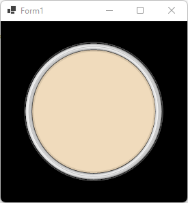
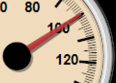
The output of the code we’re about to walk through looks like this: (the class creates the bitmap)
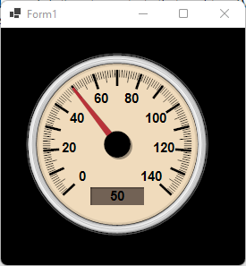
It’s not identical. I chose not to invest lots of time in the “chrome” outer edge and I used a little artistic license. The digital LCD shows the exact speed, whereas the needle is analogue and therefore has to travel. It doesn’t just “appear” at the target speed, it moves realistically.
Apologies for the grainy image, it appears to be how the app recording it chooses to create the .gif.
If you are too excited and just want to see the code, please see GitHub.
How to draw a speedo
Let’s start off with a form containing an image –
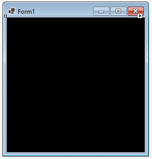
And to that, we add some code to call our “speedo” drawing class –
namespace Speedo;

public partial class Form1 : Form
{
    int speed = 0;
    int dir = 1;

    public Form1()
    {
        InitializeComponent();

        timer1.Enabled = true;
        timer1.Interval = 20;
        timer1.Tick += Timer1_Tick;
    }

    private void Timer1_Tick(object? sender, EventArgs e)
    {
        speed += dir;
        if (speed < 1 || speed > 139) dir = -dir;

        Bitmap b = DashboardSpeedometer.DrawNeedle(new Point(pictureBox1.Width / 2, pictureBox1.Height / 2), speed);

        pictureBox1.Image?.Dispose();
        pictureBox1.Image = b;
    }
}
This little snippet makes the timer fire every 20ms, and when it does it moves the needle in the current direction. When it reaches the limit (140 or 0) it reverses direction. That’s what the animation above is based on.
You might wonder if the name “DrawNeedle” should be “DrawSpeedo” and my autistic answer is no. It asks for a needle to be drawn. It doesn’t draw the speedo each time, it draws a needle. It just so happens the needle is kind enough to draw the speedo behind the needle.
The method called is defined as this.
 /// <summary>
 /// Draws the speedo needle and speedo if necessary.
 /// </summary>
 /// <param name="center">Centre of the dial.</param>
 /// <param name="speed">Speed to represent using the needle and LCD display.</param>
 internal static Bitmap DrawNeedle(Point center, double speed)
 {
   // if we haven't painted the background, we need to do that first.
   s_backgroundSpeedo ??= DrawSpeedoFace(center);

   Bitmap bitmapSpeedo = new(s_backgroundSpeedo);
Drawing the speedo without markings
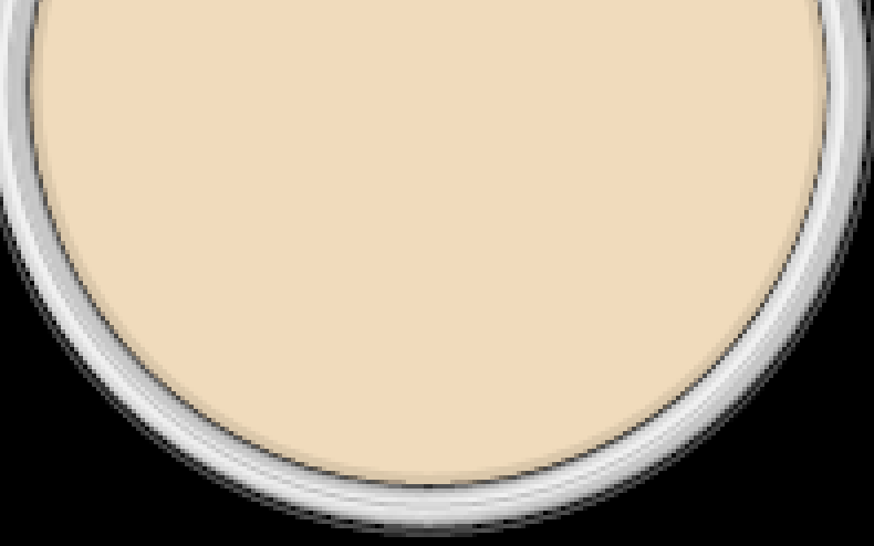
If we look at the original, it has a chrome background, which we’ll roughly approximate to grey/silver with highlights, and I beige face. I wouldn’t describe the chrome edge as a colour per se, it’s a very shiny metal and the effect comes from how it is curved and reflects light. Ray tracing and other fancy effects I shall leave to the reader. FYI, it is not a paint tin with the lid off!
The code is relatively simple leveraging alpha-transparency.
/// <summary>
/// This provides the face of the gauge, with a nice edging.
/// </summary>
/// <param name="graphics"></param>
/// <param name="cx"></param>
/// <param name="cy"></param>
private static void DrawGaugeCircleWithMetalEdge(Graphics graphics, int cx, int cy)
{
  // black around the gauge
  graphics.DrawEllipse(new Pen(Color.FromArgb(160, 200, 200, 200), 1), cx - 101, cy - 101, 101 * 2, 101 * 2);
  graphics.DrawEllipse(new Pen(Color.FromArgb(190, 0, 0, 0), 5), cx - 99, cy - 99, 99 * 2, 99 * 2);
  graphics.DrawEllipse(new Pen(Color.FromArgb(230, 0, 0, 0), 4), cx - 98, cy - 98, 98 * 2, 98 * 2);
  graphics.DrawEllipse(new Pen(Color.Black, 2), cx - 96, cy - 96, 96 * 2, 96 * 2);

  // draw the beautiful background colour for the gauge.
  graphics.FillEllipse(new SolidBrush(Color.FromArgb(240, 219, 188)), cx - 90, cy - 90, 180, 180);

  // add a subtle shadow
  graphics.DrawEllipse(new Pen(Color.FromArgb(50, 0, 0, 0), 5), cx - 90, cy - 90, 180, 180);

  // draw the 3d looking metal around the gauge. This was the result of trial and error.
  graphics.DrawEllipse(new Pen(Color.FromArgb(255, 150, 150, 150), 9), cx - 95, cy - 95, 190, 190);
  graphics.DrawEllipse(new Pen(Color.FromArgb(255, 200, 200, 200), 7), cx - 95, cy - 95, 190, 190);
  graphics.DrawEllipse(new Pen(Color.FromArgb(255, 220, 220, 220), 5), cx - 97, cy - 95, 190, 190);
  graphics.DrawEllipse(new Pen(Color.FromArgb(255, 240, 240, 240), 3), cx - 96, cy - 95, 190, 190);

  graphics.DrawEllipse(new Pen(Color.FromArgb(10, 0, 0, 0), 2), cx - 95 + 1, cy - 95 + 1, 190, 190);

  graphics.DrawEllipse(new Pen(Color.FromArgb(100, 0, 0, 0), 1), cx - 95, cy - 95, 190, 190);
}
Does it seem like a lot of circles? We need one to draw a shadow (the dark inner line), a line for the grey, and lots of lines for the highlights. Plus we need our beige filled area for which we use .FillEllipse().
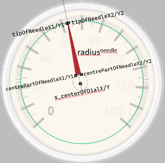
Next, we need to draw the markings and label the numbers. To explain this, let’s annotate the dial face:
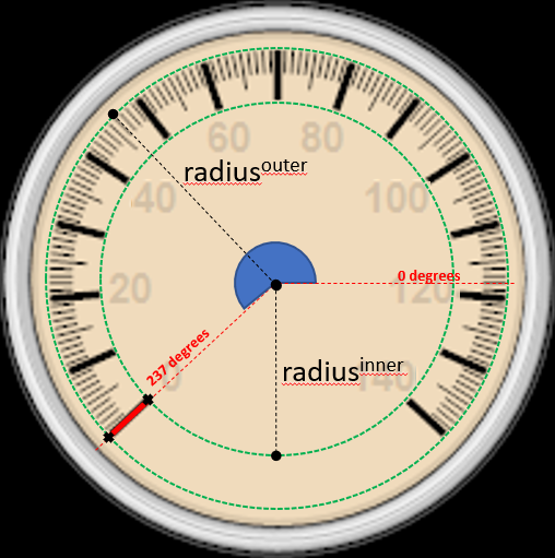
This is where we have to use a little high school mathematics. If you’re unfamiliar and the below doesn’t make sense, please Google “sine circle”.
Picture a line coming out the centre of the dial at 237 degrees, we intersect the 2 green circle lines, outer and inner radii. If we drew the line that long it would look a bit odd, and not a “graduation” on the dial.
To mark the first graduation what we need is to draw a line between the crosses. The way to work out using image upside down non-cartesian coordinates is:
- Xouter for outerradius = radiusouter * Math.Cos(237 degrees)
- Youter for outerradius = radiusouter * Math.Sin(237 degrees)
- Xinner for innerradius = radiusinner * Math.Cos(237 degrees)
- Yinner for innerradius = radiusinner * Math.Sin(237 degrees)
Draw a line between (Xouter,Youter) to (Xinner,Yinner) and you have a “graduation” mark drawn.
Tip: The input to Math.Sin()/Cos() in C# is the angle in RADIANS (2xPI=360 DEGREES). There is a good reason “radians” exist and how the value comes about. I am embarrassed to say that I have gotten caught out more than once mixing the two; so all my very latest code has the suffix RADIANS or DEGREES in the variable/input name.
What makes it a major graduation, minor or in between is simply whether you draw a thin or fat line (major), and the length of the line (minor=1/2, in between = 3/4, major=1).
It’s that simple. Draw the line, change the angle, and repeat.
Adding the speed digits is the same process, except you’re writing text at the location not drawing lines.
The code is as follows:
double cos, sin;

s_centerOfDial = center;

int cx = center.X;
int cy = center.Y;

using Pen penMajorGraduations = new(Color.Black, 3); // thicker lines for 10, 20, 30, 40
using Pen penMinorGraduations = new(Color.Black, 1); // thin lines 1, 2, 3.. 9. We make 5 slightly longer.

float sweepAngle10mphSweepsOnDial = c_needleSweepDegrees / (c_maxMPHonDial / 10);

int mphToDrawOnDial = 0;

// drawn around a dial
//
// major graduations (every 10 mph)
// |....:....|....:....|....:....|...
// ^         ^         ^         ^
// 0         10        20        30
// 0         --        20        --  we write "0" and every "20" (aesthetics)
for (float angle10mph = 0; angle10mph <= c_needleSweepDegrees; angle10mph += sweepAngle10mphSweepsOnDial)
{
	float angle1mphRequires = sweepAngle10mphSweepsOnDial / 10;

	int count = 0;

	float angleLine = angle10mph + c_needleStartDegrees;

	// |....:....|....:....|....:....|...
	//  [-------] [-------] [-------] [--  each are a "sweep"
	for (float angle1mph = 0; angle1mph < sweepAngle10mphSweepsOnDial; angle1mph += angle1mphRequires)
	{
		if (angleLine + angle1mph >= c_needleSweepDegrees + 133) continue;

		double angleInRadians = MathUtils.DegreesInRadians(angleLine + angle1mph);

		// we use this twice, as we're drawing a line from the outer-edge inwards (think of it as part of the radius)
		cos = Math.Cos(angleInRadians);
		sin = Math.Sin(angleInRadians);

		//      +         +         +   draw lines at these points
		// |....:....|....:....|....:....|...
		//      ^ count==5^      ^ count != 5
		int r = 75 - (count == 5 ? 5 : 0); // 5 = halfway between 10 markings, we make this LONGER

		graphics.DrawLine(penMinorGraduations,
                                  (float)(cx + 83 * cos), (float)(cy + 83 * sin),
                                  (float)(cx + r * cos), (float)(cy + r * sin));

		++count; // so we know which marking it is.
	}

	cos = Math.Cos(MathUtils.DegreesInRadians(angleLine));
	sin = Math.Sin(MathUtils.DegreesInRadians(angleLine));

	// |....:....|....:....|....:....|...
	// ^         ^         ^         ^ draw these
	graphics.DrawLine(penMajorGraduations,
                          (float)(cx + 83 * cos), (float)(cy + 83 * sin),
                          (float)(cx + 65 * cos), (float)(cy + 65 * sin));

	// we've chosen to draw every 20 mph (i.e. 0, 20, 40, 60 .. 140). It looks more beautiful than cramming in every 10.
	if (mphToDrawOnDial % 20 == 0)
	{
		string speedAsString = mphToDrawOnDial.ToString();
		SizeF size = graphics.MeasureString(speedAsString, s_dialFont); // we need to adjust positioning based on text size

		// positioning digits next to graduations requires the same radius rotation logic as drawing the line, just with a smaller radius.
		graphics.DrawString(speedAsString, s_dialFont, Brushes.Black,
                                    (float)(cx + 53 * cos) - size.Width / 2, (float)(cy + 53 * sin) - size.Height / 2);
	}

	mphToDrawOnDial += 10; // each graduation is worth 10mph
}
We now need the centre part the needle is attached to. We get away with drawing it with its shadow, but ideally, the shadow it casts should be on top of the needle (in the below image if the needle was round at 140 the shadow should go on top of the needle. This was a conscious choice/shortcut. You can move it to the needle drawing part if you want.

graphics.FillEllipse(new SolidBrush(Color.FromArgb(160, 0, 0, 0)),
                     cx - 15 + 2, cy - 15 + 2,
                     30, 30); // subtle shadow from centre

graphics.FillEllipse(new SolidBrush(Color.Black),
                     cx - 15, cy - 15,
                     30, 30);
The last part for the face is the liquid-crystal display area. I was quite pleased with the look of this, especially with how little effort it took. The first step was to use an eye-dropper in MSPaint against a real LCD to obtain an RGB of (114, 98, 85).
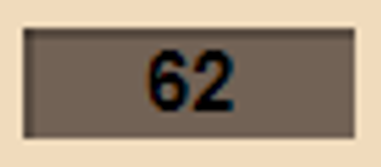
I noticed because it is recessed, you have a shadow top left / bottom right. One could pick a colour and draw, I used an alpha transparency for the effect.
 // calculate the LCD gauge
s_digitalLCDGauge = new RectangleF(cx - 30, cy + c_sizeOfDial * 0.4F + 10, 60, 20);

// [  89  ], colour acquired from photo of LCD
graphics.FillRectangle(new SolidBrush(Color.FromArgb(114, 98, 85)), s_digitalLCDGauge);

// shadow top and left of LCD (consistent with other shadows)
graphics.DrawLine(new Pen(Color.FromArgb(100, 0, 0, 0), 2),
		   s_digitalLCDGauge.X, s_digitalLCDGauge.Y + 1,
		   s_digitalLCDGauge.X + s_digitalLCDGauge.Width, s_digitalLCDGauge.Y + 1);

graphics.DrawLine(new Pen(Color.FromArgb(100, 0, 0, 0), 2),
		   s_digitalLCDGauge.X + 1, s_digitalLCDGauge.Y,
		   s_digitalLCDGauge.X + 1, s_digitalLCDGauge.Y + s_digitalLCDGauge.Height);
You’ve got yourself a speedo dial.
It took far longer to explain than it took to code!
Drawing the needle
Drawing a needle uses the same rotation about a point used to draw the graduations. But it is a trapezium, with a shadow. We therefore actually compute 4 points.
The shadow uses a little bit of a cheat. It’s not accurate physics-wise, but good enough for our purposes.
The needle is analogue, so we need to prevent it from jumping to the current “speed” – it has to travel there. The “damping” is done by clamping the desired speed to +/- maxNeedleDeflectionAllowed.
E.g., if the speed is 50, and the thing speeds up very quickly to 55 and remains at 55, then on the first frame we’ll do 55.Clamp(50-1,50+1) which is 51. Now our last speed is 51. In the next frame we do 55.Clamp(51-1,51+1), which is 52. etc. 5 frames later we’re showing 55. The needle thus “travels” 50 to 55 over multiple frames.
The LCD “digital” is instant registering 55 from frame 1.
const int maxNeedleDeflectionAllowed = 1;

// damp the needle, by only allowing it to move by a limited amount. It will always eventually reach the speed unless the speed reduces.
s_lastSpeedDialIndicates = MathUtils.Clamp(speed,
                                           s_lastSpeedDialIndicates - maxNeedleDeflectionAllowed,
                                           s_lastSpeedDialIndicates + maxNeedleDeflectionAllowed);
Plotting the needle requires us to map speed to position on the speedo. Think of it as 0-140 is the spread between the start angle and the end angle. So each “mph” or whatever the unit it works out as speed / maxSpeed * (maxAngleOfSweep-minAngleOfSweep) or more simply multiply and add the start angle:
// the range is 0..140 spread over 270 degrees, starting at (c_needleStartDegrees approx 137 degrees)
double angle = c_needleStartDegrees + (s_lastSpeedDialIndicates / 140 * (c_needleSweepDegrees - 5));
To compute the shape of the needle we need to do it as follows.
- bottom two points use radius of centre pivot. The key here is the angle is from the centre to the radius, but at an angle of +/-14 degrees is required to make it triangular.
- top points use radiusneedle, separated +/-1 degree. It is a small amount, but improves the look – the needles are not usually sharp.
if (angle < 0) angle += 360;
if (angle > 360) angle -= 360;

// alas my brain works in degrees, and sin/cos require radians. (yes 2*PI=360, but whatever)
double angleRadians = MathUtils.DegreesInRadians(angle);

// we're painting a needle. It isn't quite a triangle (more a stretched trapezium), the point has a
// thickness of +/- 0.5 which is thick enough, so we require 2 points
double dialTriangleAngleTip = 0.5 * 0.0349066F;  // radians :)

// size of dial - 15px means it points into the small graduations
float tipOfNeedleX1 = (float)Math.Cos(angleRadians - dialTriangleAngleTip) * (c_sizeOfDial - 15) + s_centerOfDial.X;
float tipOfNeedleY1 = (float)Math.Sin(angleRadians - dialTriangleAngleTip) * (c_sizeOfDial - 15) + s_centerOfDial.Y;

float tipOfNeedleX2 = (float)Math.Cos(angleRadians + dialTriangleAngleTip) * (c_sizeOfDial - 15) + s_centerOfDial.X;
float tipOfNeedleY2 = (float)Math.Sin(angleRadians + dialTriangleAngleTip) * (c_sizeOfDial - 15) + s_centerOfDial.Y;

int dialCenterRadius = 15;

// this defines the angle split between the edges of the needle
double dialTriangleAngle = 7 * 0.0349066F; // radians

// two points where it connects to the center dial.
float centrePartOfNeedleX1 = s_centerOfDial.X + (float)Math.Cos(angleRadians - dialTriangleAngle) * dialCenterRadius;
float centrePartOfNeedleY1 = s_centerOfDial.Y + (float)Math.Sin(angleRadians - dialTriangleAngle) * dialCenterRadius;

float centrePartOfNeedleX2 = s_centerOfDial.X + (float)Math.Cos(angleRadians + dialTriangleAngle) * dialCenterRadius;
float centrePartOfNeedleY2 = s_centerOfDial.Y + (float)Math.Sin(angleRadians + dialTriangleAngle) * dialCenterRadius;

PointF[] pointsForNeedle = {
   new PointF(centrePartOfNeedleX1, centrePartOfNeedleY1),
   new PointF(tipOfNeedleX1, tipOfNeedleY1),
   new PointF(tipOfNeedleX2, tipOfNeedleY2),
   new PointF(centrePartOfNeedleX2, centrePartOfNeedleY2) };

graphics.FillPolygon(s_needleBrush, pointsForNeedle); // the needle
The shadow of the needle, is the same points as the needle but shifted right 2px, and down 2px. It’s also not accurate physics wise, but good enough for our purposes (it looks convincing enough).
If you would like to take perfection to the next level, please suggest a way to do it more accurately.
// same as needle but a very simple +2 offset shadow. Technically it's wrong, as the amount of shadow depends on where the light source is in
// respect to the needle, but that's too much effort for now to fix.
PointF[] pointsForShadowUnderNeedle = {
   new PointF(centrePartOfNeedleX1 + 2, centrePartOfNeedleY1 + 2),
   new PointF(tipOfNeedleX1 + 2, tipOfNeedleY1 + 2),
   new PointF(tipOfNeedleX2 + 2, tipOfNeedleY2 + 2),
   new PointF(centrePartOfNeedleX2 + 2, centrePartOfNeedleY2 + 2) };

// triangle-ish needle (point is flattened, so trapezium)
graphics.FillPolygon(s_needleShadowBrush, pointsForShadowUnderNeedle); // shadow beneath the needle
Please note the importance of the order of painting. The shadow is drawn before the needle, otherwise it would look very odd having the needle’s shadow on top of it rather than beneath.
Writing on the LCD display
This is the easiest part, simply .DrawString() using StringFormat of .LineAlignment = Center, and .Alignment = Center.
// write the speed to the LCD
graphics.DrawString(Math.Round(speed).ToString(),
                    s_dialFont,
                    s_LCDFontColor,
                    new RectangleF(s_digitalLCDGauge.X, s_digitalLCDGauge.Y + 2, //+2, as it doesn't quite look centred vertically
                                   s_digitalLCDGauge.Width, s_digitalLCDGauge.Height - 2),
                    s_sfDigitalLCDGauge);
My only small criticism is that the intention was to make it 100% scalable (you provide the size). However whilst I set out for it to work that way, in the interest of time I didn’t change the few additional places to enable it to scale.
Do you like it? Was this post useful? Is there a better way? Please let me know in the comments.